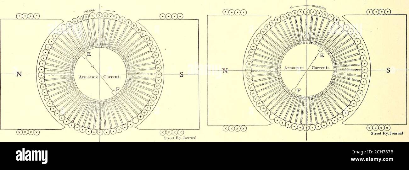
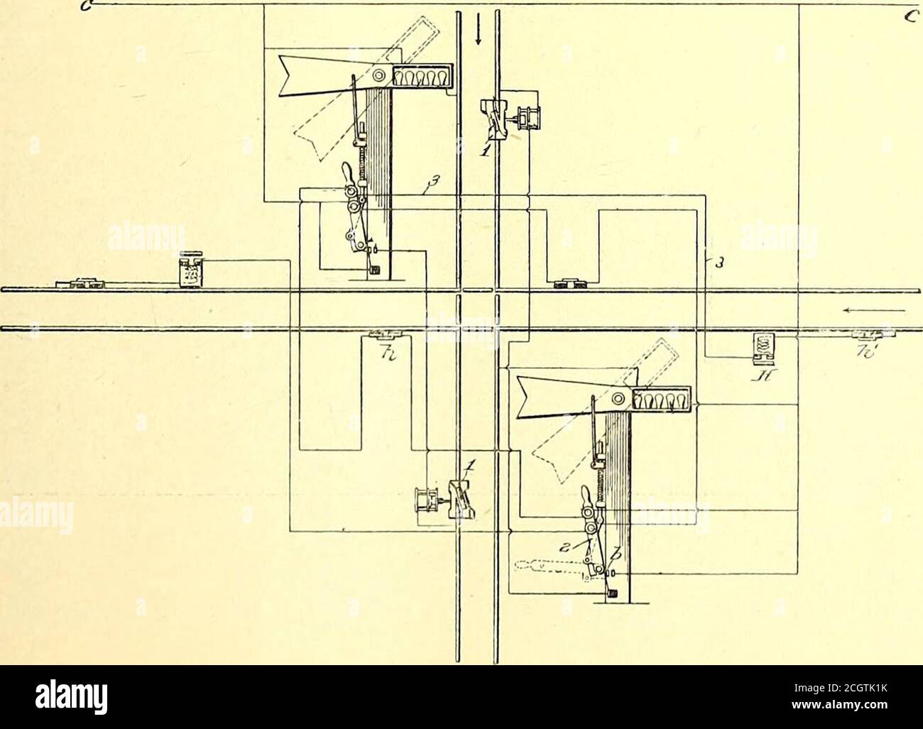
The Street railway journal . FIG. 2.—CURRENT DISTRIBUTION WITH BRUSHESOPPOSITE POLES Street Ry.Joumal FIG. 3.—CURRENT DISTRIBUTION WITH BRUSHES MIDWAYBETWEEN POLES. FIG, 4.—CURRENT DISTRIBUTION WITH BRUSHES AT ANGLEWITH NEUTRAL POINT This is
By A Mystery Man Writer
Download this stock image: . The Street railway journal . FIG. 2.—CURRENT DISTRIBUTION WITH BRUSHESOPPOSITE POLES Street Ry.Joumal FIG. 3.—CURRENT DISTRIBUTION WITH BRUSHES MIDWAYBETWEEN POLES. FIG, 4.—CURRENT DISTRIBUTION WITH BRUSHES AT ANGLEWITH NEUTRAL POINT This is true till the brush begins to cut out torque-producingwires. As soon as this happens 2 V K 1 S 180 —nT= f n —2 I V FIG, ©CsXsX*) Street Ry.Journal -CURRENT DISTRIBUTION WITH BRUSHES AT ANGLEWITH NEUTRAL POINT R 2 VKf ) 180 —2 V 360 V K f 4 V2 K f R R differentiating d T 360 K f 8 V K f dV o for a maximum R whence R360 V = = 45c In practice the position - 2CH787B from Alamy's library of millions of high resolution stock photos, illustrations and vectors.

Ch3 Willyam Hayt
Solved 1.35 Suppose there is no power lost in the wires used

PDF) Civil Engineering Formulas 2nd Edition
Solved The magnetic field in the region between the poles of
Solved THESE QUESTIONS ARE FROM THE SUBJECT ELECTRICAL

I 360 hi-res stock photography and images - Page 23 - Alamy
I 360 hi-res stock photography and images - Page 23 - Alamy

Westinghouse Brake & Saxby Signal Co. Ltd. Signalling - Track
Vol. I - Direct Current (DC) - DC Network Analysis - Branch Current Method

Estimating Static and Dynamic Stress Distribution in a Railway
SQUARE D, 1 Poles, Miniature Distribution Block

SQUARE D Miniature Distribution Block: 1 Poles, Surface Mount

FIGURE EX29.37 is a cross section through three long wires with l

I 360 hi-res stock photography and images - Page 23 - Alamy
Booksubjectstreetr hi-res stock photography and images - Page 7
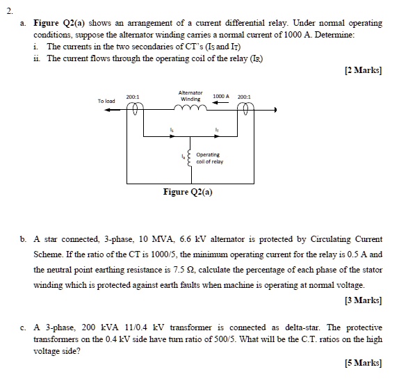
SOLVED: a. Figure Q2(a) shows an arrangement of a current
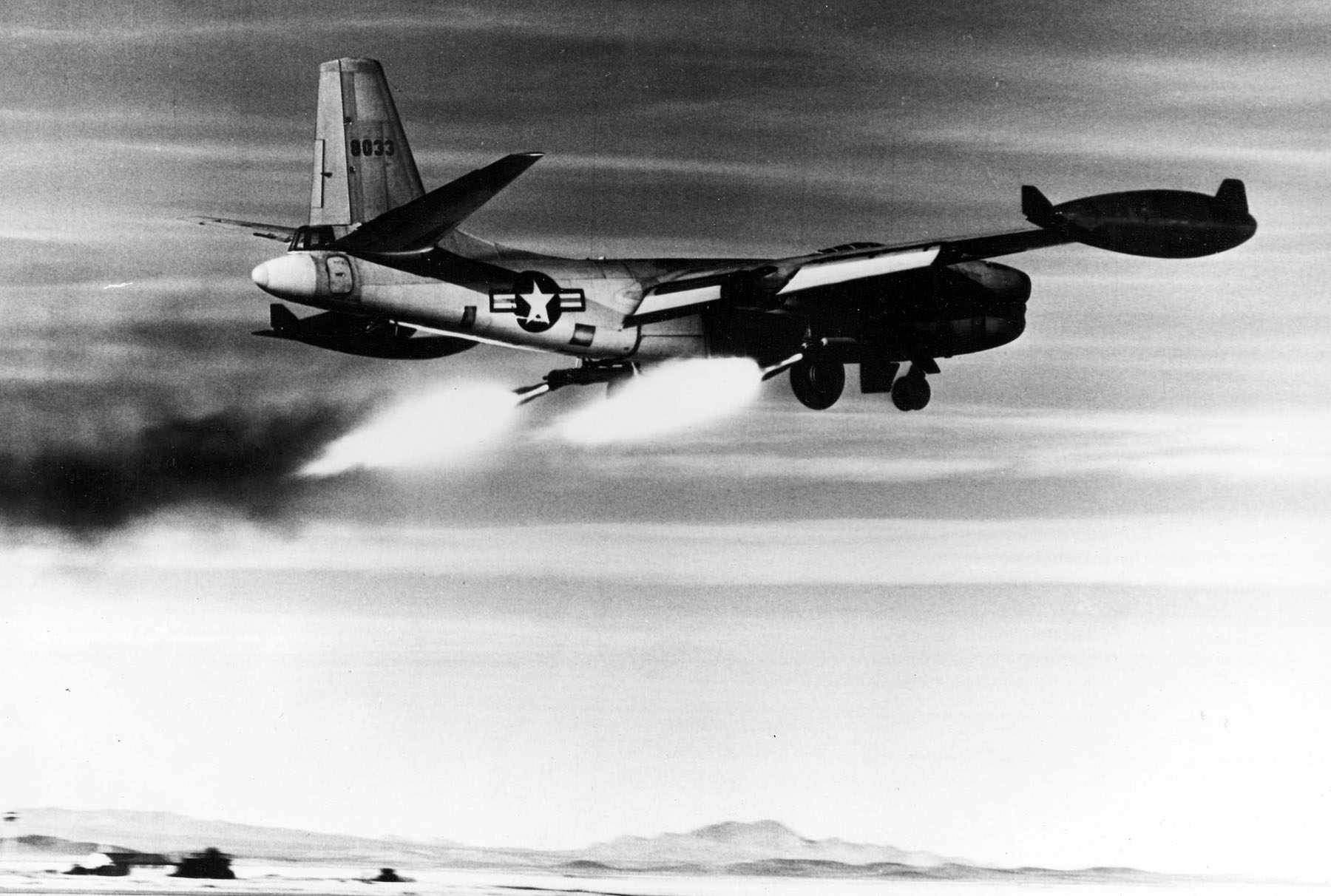
- File:North American RB-45C (SN 48-033) rocket-assisted take off. 061023-F-1234S-014.jpg - Wikimedia Commons
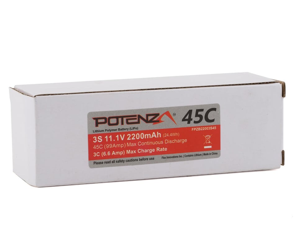
- Flex Innovations Potenza 3S LiPo Battery 45C (11.1V/2200mAh) w/EC3 Connector
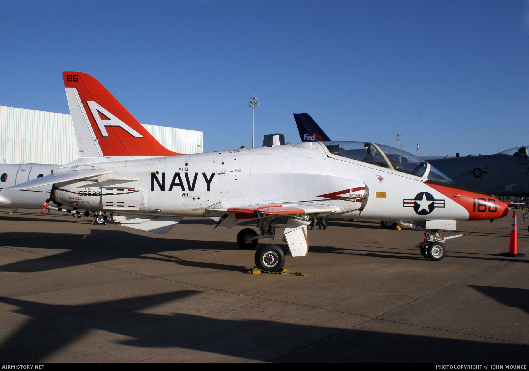
- 163650 T-45C VT-86/TAW-6 F-600, NAS Pensacola 2019 Airshow

- Aircraft Photo of 165628, McDonnell Douglas T-45C Goshawk, USA - Navy
- CAMARA KENDA 700 45C